
Page 54 - Optofluidics Fundamentals, Devices, and Applications
P. 54
Optical Components Based on Dynamic Liquid-Liquid Interfaces 35
injected continuously into the channel. The rate of flow is sufficiently
small such that the flow is laminar.
To couple light into and out of the L devices, external lenses can be
2
used to focus light from an off-chip light source into the microchannel
across the polydimethylsiloxane (PDMS) wall. Alternatively, light can
be coupled into an optical fiber, which is then inserted into the PDMS
device through appropriate ports. The use of fibers facilitates optical
alignment between external light sources, or detectors, and the micro-
fluidic channel, and allows substantial flexibility in system design. It is
2
therefore a common way of introducing light into L devices.
Ports for insertion of optical fiber (Fig. 3-2) are often included in
the design of L devices [1]; they are fabricated at the same time as the
2
rest of the microchannels. Light introduced through these inserted
fibers is in the same plane of the microchannels. The port for the
optical fiber is usually left sealed in the PDMS during the fabrication
of the device; this port is opened later by cutting the back part of the
PDMS device Microchannel
x
x
x′ x′
Embedded Fiber port
fiber port opened
(a)
Optical fiber
Fiber port
Fluid inlets
Fluid outlet 300 μm
(b) (c)
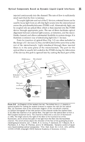
FIGURE 3-2 (a) Diagram of the sealed channel. The dotted line (x -x’) depicts a
typical location for cutting the sealed channel to expose the inlet for the optical
fi ber. (b) Top-down view of the schematic diagram of the microfl uidic channel.
(c) Optical micrograph of the inlet portion of the channel inside the dashed lines
in (b) after the insertion of an optical fi ber. The light from the optical fi ber is from a
fi ber-coupled deuterium lamp. The channel is fi lled with a solution of fl uorescein
(1 mM). The bright area to the right of the fi ber is the fl uorescence of the
fl uorescein, and it shows the path of the light from the fi ber into the fl uid-fi lled
channel. The small arrows depict the direction of the fl ow of the guiding-liquid and
cladding-liquid streams. [(D. J. Wolfe, R. S. Conroy, P. Garstecki, B. T. Mayers, M. A.
Fischback, K. E. Paul, M. Prentiss, and G. M. Whitesides, “Dynamic control of liquid
core/liquid-cladding optical waveguides,” Proc. Natl. Acad. Sci. U.S.A., 101, (2004),
12434–12438. (Copyright 2004) National Academy of Sciences, U.S.A).]