
Page 161 - Organic Electronics in Sensors and Biotechnology
P. 161
138 Cha pte r F o u r
1E–5
P(VDF-TrFE) on Melinex ®
10
Pyroelectric response (A/W) 1E–7 1 Pyroelectric response (V/W)
1E–6
1E–8 0.1
f co,MB f co,LI d = 300 nm
0.01
0.01 0.1 1 10 100 1000 10,000
Frequency (Hz)
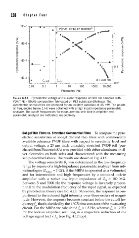
FIGURE 4.11 Pyroelectric voltage and current response of 300 nm samples with
VDF:TrFE = 55:45 composition fabricated on PET substrate (Melinex). The
pyroelectric sensitivities are obtained for an incident radiation of 45 mW. The points
at frequencies below 1 Hz were obtained with a high input impedance parametric
analyzer. The cutoff frequencies for measurement with lock-in amplifi er and
parametric analyzer are indicated, respectively.
Sol-gel Thin Films vs. Stretched Commercial Films To compare the pyro-
electric sensitivities of sol-gel derived thin films with commercially
available reference PVDF films with respect to sensitivity level and
output voltage, a 25 μm thick uniaxially stretched PVDF foil (pur-
chased from Piezotech SA) was provided with either aluminum or sil-
ver electrodes on both sides and characterized with the measuring
setup described above. The results are shown in Fig. 4.12.
The voltage sensitivity R was determined in the low-frequency
V
range by means of a high-impedance parametric analyzer from mb-
technologies (Z = 1 GΩ, if the MBPA is operated as a voltmeter)
MBPA
and for intermediate and high frequencies by a standard lock-in
amplifier with a rather low input impedance of Z = 100 MΩ.
LI
Between 5 and 5000 Hz the response voltage is inversely propor-
tional to the modulation frequency of the input signal, as expected
by pyroelectric theory (see Eq. 4.25). Moreover, the response is pro-
portional to the infrared light intensity over three orders of magni-
tude. However, the response becomes constant below the cutoff fre-
quency f that is decided by the 1/CR time constant of the measuring
co
circuit. For the MBPA we calculated f = 1.5 Hz, whereas f = 12 Hz
co co
for the lock-in amplifier, resulting in a respective reduction of the
voltage signal for f < f (see Fig. 4.12 top).
co