
Page 162 - Organic Electronics in Sensors and Biotechnology
P. 162
Integrated Pyr oelectric Sensors 139
9
100 Z MBPA = 10 Ω
Voltage sensitivity (V/W) 10 1 Laser code PVDF-sensor Z LI = 10 Ω 4.0 μm
8
Lock-in
amplifier
Waveform
generator
0.1
Computer
0.01
MBPA V ~ 1/ω
Lock in
1E–3
0.01 0.1 1 10 100 1000 10000
Frequency (Hz)
at 0.1 Hz with MBPA
Voltage output V sense
15.0
10.0
V Sensor (V) –5.0
5.0
0.0
–10.0
–15.0
0 10 20 30 40 50 60 70 80
Time (s)
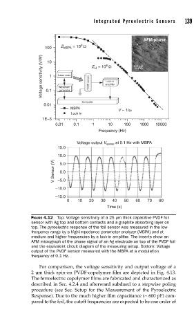
FIGURE 4.12 Top: Voltage sensitivity of a 25 μm thick capacitive PVDF foil
sensor with Ag top and bottom contacts and a graphite absorbing layer on
top. The pyroelectric response of the foil sensor was measured in the low-
frequency range by a high-impedance parameter analyzer (MBPA) and at
medium and higher frequencies by a lock-in amplifi er. The inserts show an
AFM micrograph of the phase signal of an Ag electrode on top of the PVDF foil
and the equivalent circuit diagram of the measuring setup. Bottom: Voltage
output of the PVDF sensor measured with the MBPA at a modulation
frequency of 0.1 Hz.
For comparison, the voltage sensitivity and output voltage of a
2 μm thick spin-on PVDF-copolymer film are depicted in Fig. 4.13.
The ferroelectric copolymer films are fabricated and characterized as
described in Sec. 4.2.4 and afterward subdued to a stepwise poling
procedure (see Sec. Setup for the Measurement of the Pyroelectric
Response). Due to the much higher film capacitance (~ 600 pF) com-
pared to the foil, the cutoff frequencies are expected to be one order of