
Page 249 - Organic Electronics in Sensors and Biotechnology
P. 249
226 Cha pte r S i x
i f
x R f
–
i i sh ~ ~ –iR
V out f
+
V = iR L R sh C
(a) (b)
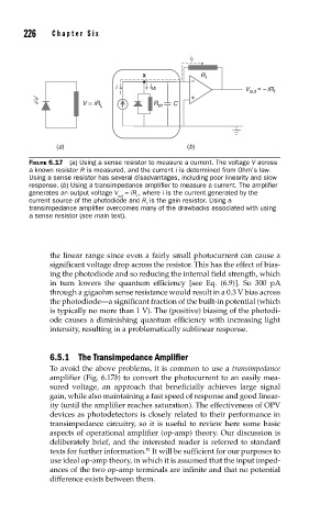
FIGURE 6.17 (a) Using a sense resistor to measure a current. The voltage V across
a known resistor R is measured, and the current i is determined from Ohm’s law.
Using a sense resistor has several disadvantages, including poor linearity and slow
response. (b) Using a transimpedance amplifi er to measure a current. The amplifi er
generates an output voltage V = iR , where i is the current generated by the
out f
current source of the photodiode and R is the gain resistor. Using a
f
transimpedance amplifi er overcomes many of the drawbacks associated with using
a sense resistor (see main text).
the linear range since even a fairly small photocurrent can cause a
significant voltage drop across the resistor. This has the effect of bias-
ing the photodiode and so reducing the internal field strength, which
in turn lowers the quantum efficiency [see Eq. (6.9)]. So 300 pA
through a gigaohm sense resistance would result in a 0.3 V bias across
the photodiode—a significant fraction of the built-in potential (which
is typically no more than 1 V). The (positive) biasing of the photodi-
ode causes a diminishing quantum efficiency with increasing light
intensity, resulting in a problematically sublinear response.
6.5.1 The Transimpedance Amplifier
To avoid the above problems, it is common to use a transimpedance
amplifier (Fig. 6.17b) to convert the photocurrent to an easily mea-
sured voltage, an approach that beneficially achieves large signal
gain, while also maintaining a fast speed of response and good linear-
ity (until the amplifier reaches saturation). The effectiveness of OPV
devices as photodetectors is closely related to their performance in
transimpedance circuitry, so it is useful to review here some basic
aspects of operational amplifier (op-amp) theory. Our discussion is
deliberately brief, and the interested reader is referred to standard
texts for further information. It will be sufficient for our purposes to
51
use ideal op-amp theory, in which it is assumed that the input imped-
ances of the two op-amp terminals are infinite and that no potential
difference exists between them.