
Page 327 - Orlicky's Material Requirements Planning
P. 327
306 PART 3 Managing with the MRP System
and the basis on which MRP was developed is to first plan the priorities of the enterprise
and then to confirm the capacity availability.
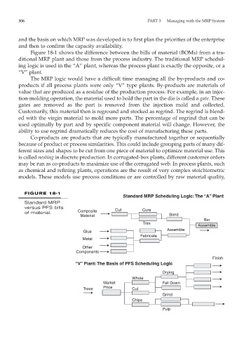
Figure 18-1 shows the difference between the bills of material (BOMs) from a tra-
ditional MRP plant and those from the process industry. The traditional MRP schedul-
ing logic is used in the “A” plant, whereas the process plant is exactly the opposite, or a
“V” plant.
The MRP logic would have a difficult time managing all the by-products and co-
products if all process plants were only “V” type plants. By-products are materials of
value that are produced as a residue of the production process. For example, in an injec-
tion-molding operation, the material used to hold the part in the die is called a gate. These
gates are removed as the part is removed from the injection mold and collected.
Customarily, this material then is reground and stocked as regrind. The regrind is blend-
ed with the virgin material to mold more parts. The percentage of regrind that can be
used optimally by part and by specific component material will change. However, the
ability to use regrind dramatically reduces the cost of manufacturing these parts.
Co-products are products that are typically manufactured together or sequentially
because of product or process similarities. This could include grouping parts of many dif-
ferent sizes and shapes to be cut from one piece of material to optimize material use. This
is called nesting in discrete production. In corrugated-box plants, different customer orders
may be run as co-products to maximize use of the corrugated web. In process plants, such
as chemical and refining plants, operations are the result of very complex stoichiometric
models. These models use process conditions or are controlled by raw material quality,
FIGURE 18-1
Standard MRP Scheduling Logic: The “A” Plant
Standard MRP
versus PFS bills Cut Cure
of material. Composite
Material Bond
Bin
Trim
Assemble
Assemble
Glue
Fabricate
Metal
Other
Components
Finish
“V” Plant: The Basis of PFS Scheduling Logic
Drying
Whole
Market Fall Down
Trees Price Cut
Grind
Chips
Pulp