
Page 158 - PDA Robotics Using Your Personal Digital Assistant to Control Your Robot
P. 158
PDA 06 5/27/03 8:37 AM Page 134
PDA Robotics
the main platform. Secure a piece of sticky Velcro to the top plate
(where you would like the transceiver to go) and to the transceiver
itself. We need to program the 16F876 microcontroller, so it’s best to
leave the top plate off until this is done (see the next chapter).
The Camera (Accessory) Mount
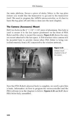
Drill two holes in the 1" 1/2" 1/4" piece of aluminum. One hole is
used to secure it to the hex spacer positioned on the front of PDA
Robot and the other to mount the camera. Figure 6.35 shows the cam-
era mount attached to the hex space. A X10 wireless video camera will
be mounted here to provide vision when PDA Robot is being con-
trolled remotely from a PC connected to the wireless network.
Figure 6.35
Camera mount
attached to the 2"
hex spacer.
Now that PDA Robot’s physical body is complete, we need to give him
a brain. Information on how to program the microcontroller and the
PDA software is in the chapters to follow. Figures 6.36 and 6.37 show
PDA Robot fully assembled.
134