
Page 154 - PDA Robotics Using Your Personal Digital Assistant to Control Your Robot
P. 154
PDA 06 5/27/03 8:37 AM Page 130
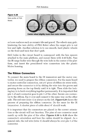
Figure 6.28
Side profile of PDA PDA Robotics
Robot.
or loose surfaces such as ceramic tile and gravel. The wheels may grab,
hindering the turn ability of PDA Robot when the carpet pile is not
low and tight. Another solution is to use smooth, hard plastic wheels
on the front and back that don’t grab.
Drill holes in the circuit board to correspond with the hex spacers
attached to the main platform, and mount them with 4-40 bolts. Pass
the IR range finder wire through the wire hole in the center of the plat-
form, and insert the presoldered wire connectors into the plastic
Molex housing.
The Ribbon Connectors
To connect the main board to the IR transceiver and the motor con-
troller, we need to prepare the ribbon connectors. For the main board
to motor controller connection, cut a 6" piece of ribbon six wires wide,
and secure the connector to it by sliding the wire into the groves and
pressing down on the top firmly until it is tight. Then slide the lock-
ing key in to hold everything together permanently. It is important that
pin 1 of each connector goes to pin 1 of the other. Secure one connec-
tor to the ribbon, flip it over and connect it the same way on the other
side. The red wire (wire 1) is always on the left. Figure 6.29 shows the
process of preparing the ribbon connector. Do the same for the IR
transceiver. A shorter piece of cable about 4" should work.
It is important that the connectors are placed in the correct orienta-
tion or the circuit will not function. The pins of one connector must
match up with the pins of the other. Figures 6.30 to 6.33 show the
connector’s orientation and how the cables should be aligned. As a
general rule, the red wire (wire 1) should always be over pin 1 of the
connector.
130