
Page 149 - PDA Robotics Using Your Personal Digital Assistant to Control Your Robot
P. 149
PDA 06 5/27/03 8:37 AM Page 125
Chapter 6 / Building PDA Robot
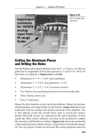
Figure 6.20
The IR analog input
connector.
Cutting the Aluminum Pieces
and Drilling the Holes
Cut the bottom plate (main platform) into an 8" 6" piece. Cut the top
plate that is suspended on four hex spacers to 7" and 5-1/4". Drill out
the holes, as outlined in Figures 6.21 and 6.22.
• Aluminum: 8" 6" 1/16" (main platform)
• Aluminum: 7" 5-1/4" (top platform) 1/16"
• Aluminum: 1" 1/2" 1/4" (accessory mount)
• Two Tamiya six-speed geared motors (www.hvwtech.com)
• Three Tamiya wheel sets
• Four 1" L-brackets
Mount the hex brackets on the top of the platform. Mount the motors,
wheel brackets, and range finder on the bottom. Figure 6.23 shows the
underside with the motors and wheels mounted to the platform. The
2" hex spacers secure the outside bolts used to mount the motors.
Ensure that both motors are oriented in the same direction. If they
aren’t, the PDA control software will have to be modified to control
the direction of PDA Robot’s motion. Figure 6.23 shows the underside
of the main platform with the motors, range finder, and wheels mount-
ed. The two pieces of balsa wood under the motor gearboxes raise the
125