
Page 144 - PDA Robotics Using Your Personal Digital Assistant to Control Your Robot
P. 144
PDA 06 5/27/03 8:37 AM Page 120
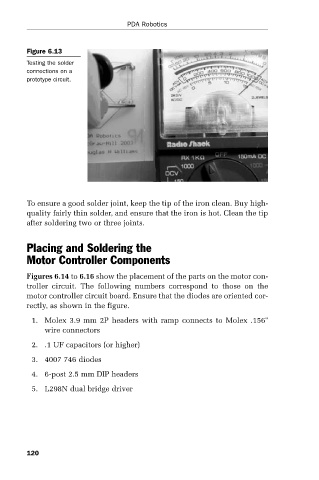
Figure 6.13
Testing the solder PDA Robotics
connections on a
prototype circuit.
To ensure a good solder joint, keep the tip of the iron clean. Buy high-
quality fairly thin solder, and ensure that the iron is hot. Clean the tip
after soldering two or three joints.
Placing and Soldering the
Motor Controller Components
Figures 6.14 to 6.16 show the placement of the parts on the motor con-
troller circuit. The following numbers correspond to those on the
motor controller circuit board. Ensure that the diodes are oriented cor-
rectly, as shown in the figure.
1. Molex 3.9 mm 2P headers with ramp connects to Molex .156"
wire connectors
2. .1 UF capacitors (or higher)
3. 4007 746 diodes
4. 6-post 2.5 mm DIP headers
5. L298N dual bridge driver
120