
Page 143 - PDA Robotics Using Your Personal Digital Assistant to Control Your Robot
P. 143
PDA 06 5/27/03 8:37 AM Page 119
Chapter 6 / Building PDA Robot
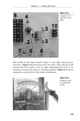
Figure 6.11
Enlarged view of
right side of main
board.
The needle on the meter should “spike” to the right, showing zero
resistance. Figure 6.12 shows the meter set to RX 1 KΩ, with the leads
crossed and the needle to the far right, indicating that there is no
resistance and that the meter is working properly. Figure 6.13 shows
testing the conductivity of the solder connections.
Figure 6.12
Setting the meter
for conductivity
testing.
119