
Page 147 - PDA Robotics Using Your Personal Digital Assistant to Control Your Robot
P. 147
PDA 06 5/27/03 8:37 AM Page 123
Chapter 6 / Building PDA Robot
epoxy, gently scrape off the photoresist (which protects the pads from
corrosion) in order to achieve a good contact. A small flathead screw-
driver works well for this. Once the solder or epoxy has set, it is a good
idea to cement the backside of the transceiver with a regular noncon-
ducting epoxy.
Set the boards aside until ready to drill the mounting holes. I recom-
mend putting them in a static-proof bag. We will mount the boards to
the craft once the other steps, such as creating the ribbon cables and
drilling the holes in the support pieces, etc., are done.
The Power Connectors
The Battery Packs
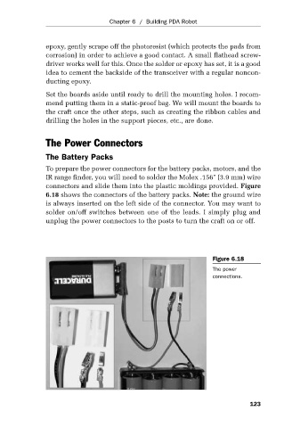
To prepare the power connectors for the battery packs, motors, and the
IR range finder, you will need to solder the Molex .156" (3.9 mm) wire
connectors and slide them into the plastic moldings provided. Figure
6.18 shows the connectors of the battery packs. Note: the ground wire
is always inserted on the left side of the connector. You may want to
solder on/off switches between one of the leads. I simply plug and
unplug the power connectors to the posts to turn the craft on or off.
Figure 6.18
The power
connections.
123