
Page 142 - PDA Robotics Using Your Personal Digital Assistant to Control Your Robot
P. 142
PDA 06 5/27/03 8:37 AM Page 118
PDA Robotics
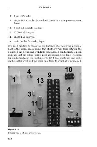
8. 8-pin DIP switch
9. 18-pin DIP IC socket (Note the PIC16F876 is using two—one cut
down)
10. 6-post 2.5 mm DIP headers
11. 20.0000 MHz crystal
12. 11.0592 MHz crystal
13. 1-pin header for analog input
It is good practice to check the conductance after soldering a compo-
nent to the board. This ensures that electricity will flow between the
points on the circuit and with little resistance. If conductivity is poor,
it means that the solder joint is poor and should be redone. To check
for conductivity, set the multimeter to RX 1 KΩ, and touch one probe
on the solder weld and the other on a trace to which it is connected.
Figure 6.10
Enlarged view of left side of main board.
118