Page 141 - PDA Robotics Using Your Personal Digital Assistant to Control Your Robot
P. 141

PDA 06  5/27/03  8:37 AM  Page 117
                                                    Chapter 6 / Building PDA Robot
                                 Placing and Soldering the
                                 Main Board Components
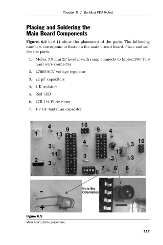
                                 Figures  6.9 to  6.11 show  the  placement  of  the  parts.  The  following
                                 numbers correspond to those on the main circuit board. Place and sol-
                                 der the parts.
                                  1. Molex 3.9 mm 2P header with ramp connects to Molex 156" (3.9
                                      mm) wire connector
                                  2. L7805ACV voltage regulator

                                  3. 22 pF capacitors
                                  4. 1 K resistors

                                  5. Red LED
                                  6. 47R 1/4 W resistors
                                  7.  4.7 UF tantalum capacitor


                                 Figure 6.9
                                 Main board parts placement.

                                                                                               117
   136   137   138   139   140   141   142   143   144   145   146