
Page 137 - PDA Robotics Using Your Personal Digital Assistant to Control Your Robot
P. 137
PDA 06 5/27/03 8:37 AM Page 113
Chapter 6 / Building PDA Robot
Removal of resist is not necessary when soldering components to the
board. By leaving the resist on, you protect the circuit from oxidation.
Tin plating the board is not necessary. In soldering, the heat disinte-
grates the resist underneath the solder, resulting in an excellent bond.
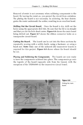
Drilling Out the Circuit Board. Once the board is dry, drill out the
holes using the appropriate drill bits. Be sure that the bit is in straight
and that you hit the hole dead center. Figure 6.6 shows the main board
being drilled out. Figure 6.7 shows the ribbon connector holes on a
transponder circuit board.
Cutting the Board. The board can be cut into the three sections by
repeatedly scoring with a utility knife, using a hacksaw, or using a
band saw. Note: Only one of the infrared (IR) transceiver boards is
required for this project. Figure 6.8 shows where the board should
be cut.
Placing and Soldering the Components. The boards are now ready
to have the components soldered into place. The components go onto
the topside of the board (opposite side from the traces), with the
exception of the TFDS4500 on the transceiver circuit board.
Figure 6.6
Drilling the main
board.
113