
Page 133 - PDA Robotics Using Your Personal Digital Assistant to Control Your Robot
P. 133
PDA 06 5/27/03 8:37 AM Page 109
Chapter 6 / Building PDA Robot
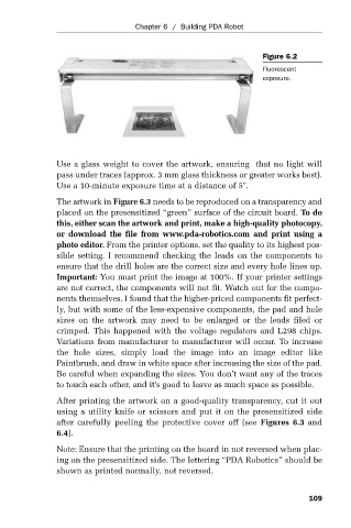
Figure 6.2
Fluorescent
exposure.
Use a glass weight to cover the artwork, ensuring that no light will
pass under traces (approx. 3 mm glass thickness or greater works best).
Use a 10-minute exposure time at a distance of 5".
The artwork in Figure 6.3 needs to be reproduced on a transparency and
placed on the presensitized “green” surface of the circuit board. To do
this, either scan the artwork and print, make a high-quality photocopy,
or download the file from www.pda-robotics.com and print using a
photo editor. From the printer options, set the quality to its highest pos-
sible setting. I recommend checking the leads on the components to
ensure that the drill holes are the correct size and every hole lines up.
Important: You must print the image at 100%. If your printer settings
are not correct, the components will not fit. Watch out for the compo-
nents themselves. I found that the higher-priced components fit perfect-
ly, but with some of the less-expensive components, the pad and hole
sizes on the artwork may need to be enlarged or the leads filed or
crimped. This happened with the voltage regulators and L298 chips.
Variations from manufacturer to manufacturer will occur. To increase
the hole sizes, simply load the image into an image editor like
Paintbrush, and draw in white space after increasing the size of the pad.
Be careful when expanding the sizes. You don’t want any of the traces
to touch each other, and it’s good to leave as much space as possible.
After printing the artwork on a good-quality transparency, cut it out
using a utility knife or scissors and put it on the presensitized side
after carefully peeling the protective cover off (see Figures 6.3 and
6.4).
Note: Ensure that the printing on the board in not reversed when plac-
ing on the presensitized side. The lettering “PDA Robotics” should be
shown as printed normally, not reversed.
109