
Page 128 - PDA Robotics Using Your Personal Digital Assistant to Control Your Robot
P. 128
PDA 05 5/30/03 11:35 AM Page 104
PDA Robotics
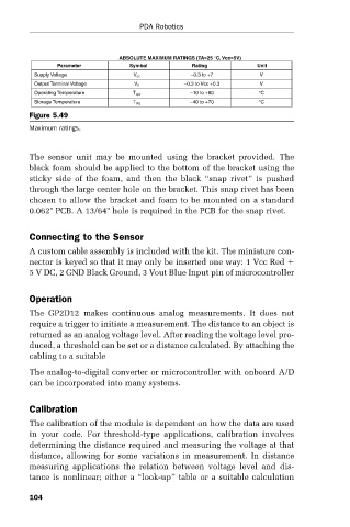
ABSOLUTE MAXIMUM RATINGS (TA=25 °C, Vcc=5V)
Parameter Symbol Rating Unit
Supply Voltage V cc –0.3 to +7 V
Output Terminal Voltage V 0 –0.3 to Vcc +0.3 V
Operating Temperature T opr –10 to +60 °C
Storage Temperature T stg –40 to +70 °C
Figure 5.49
Maximum ratings.
The sensor unit may be mounted using the bracket provided. The
black foam should be applied to the bottom of the bracket using the
sticky side of the foam, and then the black “snap rivet” is pushed
through the large center hole on the bracket. This snap rivet has been
chosen to allow the bracket and foam to be mounted on a standard
0.062" PCB. A 13/64" hole is required in the PCB for the snap rivet.
Connecting to the Sensor
A custom cable assembly is included with the kit. The miniature con-
nector is keyed so that it may only be inserted one way: 1 Vcc Red
5 V DC, 2 GND Black Ground, 3 Vout Blue Input pin of microcontroller
Operation
The GP2D12 makes continuous analog measurements. It does not
require a trigger to initiate a measurement. The distance to an object is
returned as an analog voltage level. After reading the voltage level pro-
duced, a threshold can be set or a distance calculated. By attaching the
cabling to a suitable
The analog-to-digital converter or microcontroller with onboard A/D
can be incorporated into many systems.
Calibration
The calibration of the module is dependent on how the data are used
in your code. For threshold-type applications, calibration involves
determining the distance required and measuring the voltage at that
distance, allowing for some variations in measurement. In distance
measuring applications the relation between voltage level and dis-
tance is nonlinear; either a “look-up” table or a suitable calculation
104