
Page 148 - PDA Robotics Using Your Personal Digital Assistant to Control Your Robot
P. 148
PDA 06 5/27/03 8:37 AM Page 124
PDA Robotics
The IR Range Finder
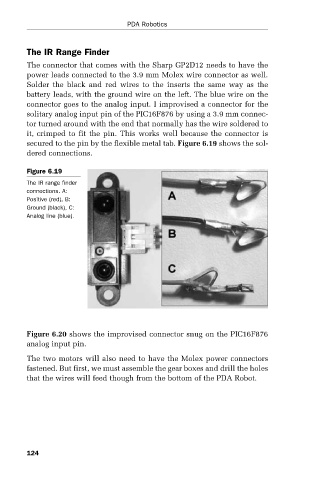
The connector that comes with the Sharp GP2D12 needs to have the
power leads connected to the 3.9 mm Molex wire connector as well.
Solder the black and red wires to the inserts the same way as the
battery leads, with the ground wire on the left. The blue wire on the
connector goes to the analog input. I improvised a connector for the
solitary analog input pin of the PIC16F876 by using a 3.9 mm connec-
tor turned around with the end that normally has the wire soldered to
it, crimped to fit the pin. This works well because the connector is
secured to the pin by the flexible metal tab. Figure 6.19 shows the sol-
dered connections.
Figure 6.19
The IR range finder
connections. A:
Positive (red), B:
Ground (black), C:
Analog line (blue).
Figure 6.20 shows the improvised connector snug on the PIC16F876
analog input pin.
The two motors will also need to have the Molex power connectors
fastened. But first, we must assemble the gear boxes and drill the holes
that the wires will feed though from the bottom of the PDA Robot.
124