
Page 67 - PDA Robotics Using Your Personal Digital Assistant to Control Your Robot
P. 67
PDA 05 5/30/03 11:35 AM Page 43
5
The
Electronics
This chapter consists of two parts. First is an overview of the electron-
ic design, focusing on various portions of the schematic diagram.
Second is a description of each component, including its function and
how it interacts with the others. The next chapter will explain step-by-
step how to create the circuit, from “burring the board” to soldering
each component.
System Overview
The circuit consists of three parts that can be separated, as I have with
this project, or kept together. The main board is connected to the
infrared (IR) transceiver and the motor controller circuit via 6-wire rib-
bon connectors. I chose to do this so that the motor circuit and the
transponder could be placed anywhere, allowing for flexibility of
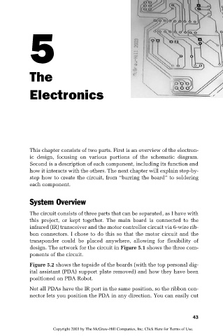
design. The artwork for the circuit in Figure 5.1 shows the three com-
ponents of the circuit.
Figure 5.2 shows the topside of the boards (with the top personal dig-
ital assistant (PDA) support plate removed) and how they have been
positioned on PDA Robot.
Not all PDAs have the IR port in the same position, so the ribbon con-
nector lets you position the PDA in any direction. You can easily cut
43
Copyright 2003 by The McGraw-Hill Companies, Inc. Click Here for Terms of Use.