
Page 68 - PDA Robotics Using Your Personal Digital Assistant to Control Your Robot
P. 68
PDA 05 5/30/03 11:35 AM Page 44
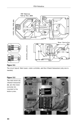
Figure 5.1 PDA Robotics
The circuit layout: Main board, motor controller, and the infrared transceiver (only one is
needed).
Figure 5.2
The main board (A),
infrared transceiver
(B), and the motor
controller (C)
mounted to the
bottom plate.
44