
Page 70 - PDA Robotics Using Your Personal Digital Assistant to Control Your Robot
P. 70
PDA 05 5/30/03 11:35 AM Page 46
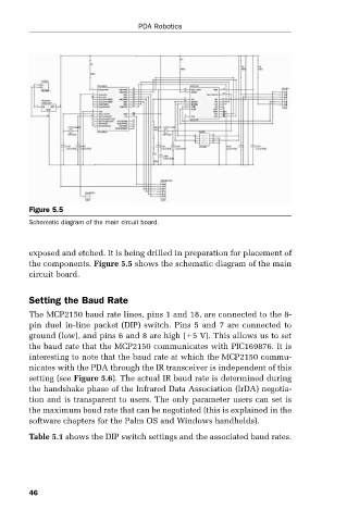
Figure 5.5 PDA Robotics
Schematic diagram of the main circuit board.
exposed and etched. It is being drilled in preparation for placement of
the components. Figure 5.5 shows the schematic diagram of the main
circuit board.
Setting the Baud Rate
The MCP2150 baud rate lines, pins 1 and 18, are connected to the 8-
pin duel in-line packet (DIP) switch. Pins 5 and 7 are connected to
ground (low), and pins 6 and 8 are high ( 5 V). This allows us to set
the baud rate that the MCP2150 communicates with PIC169876. It is
interesting to note that the baud rate at which the MCP2150 commu-
nicates with the PDA through the IR transceiver is independent of this
setting (see Figure 5.6). The actual IR baud rate is determined during
the handshake phase of the Infrared Data Association (IrDA) negotia-
tion and is transparent to users. The only parameter users can set is
the maximum baud rate that can be negotiated (this is explained in the
software chapters for the Palm OS and Windows handhelds).
Table 5.1 shows the DIP switch settings and the associated baud rates.
46