
Page 75 - PDA Robotics Using Your Personal Digital Assistant to Control Your Robot
P. 75
PDA 05 5/30/03 11:35 AM Page 51
Chapter 5 / The Electronics
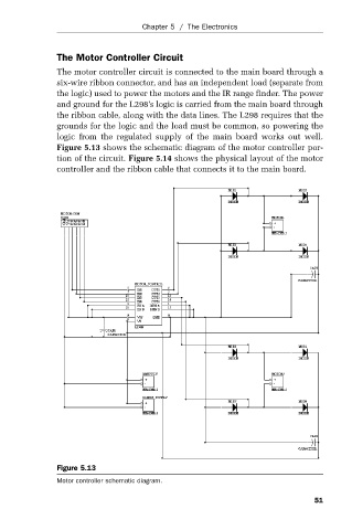
The Motor Controller Circuit
The motor controller circuit is connected to the main board through a
six-wire ribbon connector, and has an independent load (separate from
the logic) used to power the motors and the IR range finder. The power
and ground for the L298’s logic is carried from the main board through
the ribbon cable, along with the data lines. The L298 requires that the
grounds for the logic and the load must be common, so powering the
logic from the regulated supply of the main board works out well.
Figure 5.13 shows the schematic diagram of the motor controller por-
tion of the circuit. Figure 5.14 shows the physical layout of the motor
controller and the ribbon cable that connects it to the main board.
Figure 5.13
Motor controller schematic diagram.
51