Page 76 - PDA Robotics Using Your Personal Digital Assistant to Control Your Robot
P. 76

PDA 05  5/30/03  11:35 AM  Page 52
                          Figure 5.14
                          Motor controller           PDA Robotics
                          PCB motor 1
                          connector (A),
                          ribbon connector
                          (B), motor 2
                          connector (C),
                          motor power supply
                          connector (D), range
                          finder power
                          connection (E),
                          L298 motor
                          controller chip (F),
                          and diode (G).


                          The Sharp GPD12 IR Range Finder
                          The Sharp GPD12 IR range finder is connected to the first configurable
                          analog pin on the PIC16F876. Figure 5.15 shows the pin (C), which is
                          connected  to  the  analog  output  of  the  range  finder  and  the  analog
                          input of the microchip.
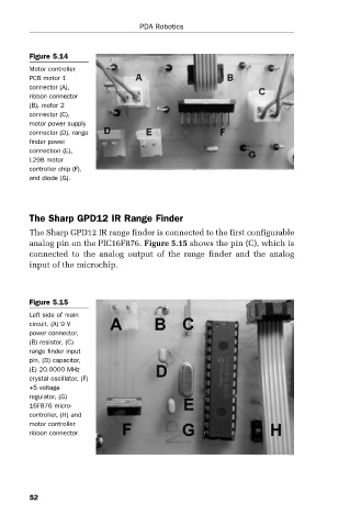


                          Figure 5.15
                          Left side of main
                          circuit, (A) 9 V
                          power connector,
                          (B) resistor, (C)
                          range finder input
                          pin, (D) capacitor,
                          (E) 20.0000 MHz
                          crystal oscillator, (F)
                          +5 voltage
                          regulator, (G)
                          16F876 micro-
                          controller, (H) and
                          motor controller
                          ribbon connector.


                          52
   71   72   73   74   75   76   77   78   79   80   81