
Page 79 - PDA Robotics Using Your Personal Digital Assistant to Control Your Robot
P. 79
PDA 05 5/30/03 11:35 AM Page 55
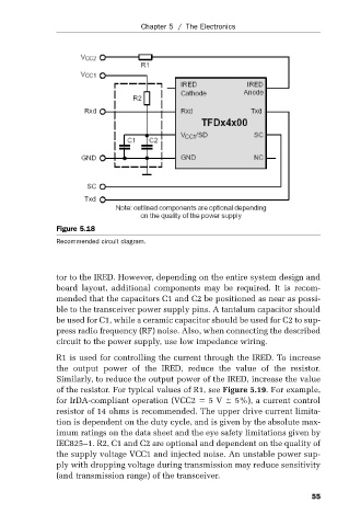
Figure 5.18 Chapter 5 / The Electronics
Recommended circuit diagram.
tor to the IRED. However, depending on the entire system design and
board layout, additional components may be required. It is recom-
mended that the capacitors C1 and C2 be positioned as near as possi-
ble to the transceiver power supply pins. A tantalum capacitor should
be used for C1, while a ceramic capacitor should be used for C2 to sup-
press radio frequency (RF) noise. Also, when connecting the described
circuit to the power supply, use low impedance wiring.
R1 is used for controlling the current through the IRED. To increase
the output power of the IRED, reduce the value of the resistor.
Similarly, to reduce the output power of the IRED, increase the value
of the resistor. For typical values of R1, see Figure 5.19. For example,
for IrDA-compliant operation (VCC2 5 V 5%), a current control
resistor of 14 ohms is recommended. The upper drive current limita-
tion is dependent on the duty cycle, and is given by the absolute max-
imum ratings on the data sheet and the eye safety limitations given by
IEC825–1. R2, C1 and C2 are optional and dependent on the quality of
the supply voltage VCC1 and injected noise. An unstable power sup-
ply with dropping voltage during transmission may reduce sensitivity
(and transmission range) of the transceiver.
55