
Page 74 - PDA Robotics Using Your Personal Digital Assistant to Control Your Robot
P. 74
PDA 05 5/30/03 11:35 AM Page 50
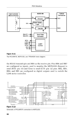
Figure 5.11 PDA Robotics
The PIC16F876, MCP2150, and TFDS4500 block diagram.
the RS232 transmit pin and RB1 as the receive pin. Pins RB6 and RB7
are configured as inputs, used to monitor the MCP2150’s Request to
send (RTS: pin 13) and Clear to send (CTS: pin 12) pins. RB2, RB3,
RB4, and RB5 are configured as digital outputs used to switch the
L298 motor controller.
Figure 5.12
Schematic of PIC16F876 connection to MCP2150.
50