
Page 73 - PDA Robotics Using Your Personal Digital Assistant to Control Your Robot
P. 73
PDA 05 5/30/03 11:35 AM Page 49
Figure 5.9 Chapter 5 / The Electronics
IR transceiver schematic.
The MCP2150 Connection to the PIC16F876
Microcontroller
The microcontroller is connected to the MCP2150 IrDA protocol stack
decoder via the microcontroller’s configurable B port. The block dia-
gram in Figure 5.11 shows the relationship between the transceiver,
the controller, and the MCP2150.
The schematic diagram in Figure 5.12 shows the actual pin connec-
tions between the PIC16F876 and the MCP2150. RBO is configured as
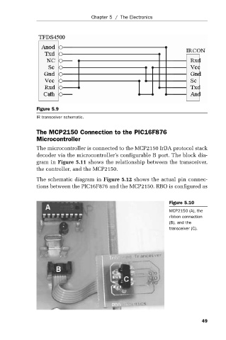
Figure 5.10
MCP2150 (A), the
ribbon connection
(B), and the
transceiver (C).
49