
Page 72 - PDA Robotics Using Your Personal Digital Assistant to Control Your Robot
P. 72
PDA 05 5/30/03 11:35 AM Page 48
Figure 5.7
PDA Robot with the PDA Robotics
baud rate set to
115200.
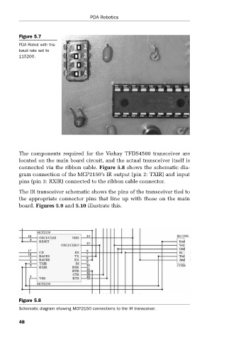
The components required for the Vishay TFDS4500 transceiver are
located on the main board circuit, and the actual transceiver itself is
connected via the ribbon cable. Figure 5.8 shows the schematic dia-
gram connection of the MCP2150’s IR output (pin 2: TXIR) and input
pins (pin 3: RXIR) connected to the ribbon cable connector.
The IR transceiver schematic shows the pins of the transceiver tied to
the appropriate connector pins that line up with those on the main
board. Figures 5.9 and 5.10 illustrate this.
Figure 5.8
Schematic diagram showing MCP2150 connections to the IR transceiver.
48