
Page 84 - PDA Robotics Using Your Personal Digital Assistant to Control Your Robot
P. 84
PDA 05 5/30/03 11:35 AM Page 60
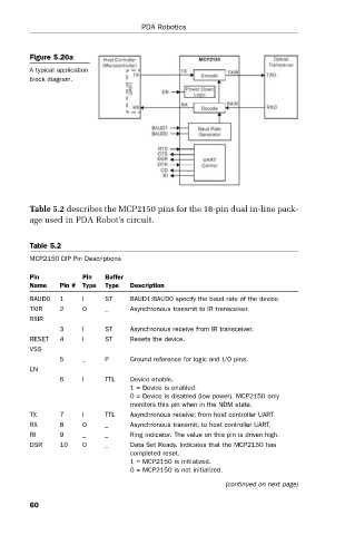
Figure 5.20a
A typical application PDA Robotics
block diagram.
Table 5.2 describes the MCP2150 pins for the 18-pin dual in-line pack-
age used in PDA Robot’s circuit.
Table 5.2
MCP2150 DIP Pin Descriptions
Pin Pin Buffer
Name Pin # Type Type Description
BAUD0 1 I ST BAUD1:BAUD0 specify the baud rate of the device.
TXIR 2 O _ Asynchronous transmit to IR transceiver.
RXIR
3 I ST Asynchronous receive from IR transceiver.
RESET 4 I ST Resets the device.
VSS
5 _ P Ground reference for logic and I/O pins.
EN
6 I TTL Device enable.
1 = Device is enabled.
0 = Device is disabled (low power). MCP2150 only
monitors this pin when in the NDM state.
TX 7 I TTL Asynchronous receive; from host controller UART.
RX 8 O _ Asynchronous transmit; to host controller UART.
RI 9 _ _ Ring indicator. The value on this pin is driven high.
DSR 10 O _ Data Set Ready. Indicates that the MCP2150 has
completed reset.
1 = MCP2150 is initialized.
0 = MCP2150 is not initialized.
(continued on next page)
60