
Page 86 - PDA Robotics Using Your Personal Digital Assistant to Control Your Robot
P. 86
PDA 05 5/30/03 11:35 AM Page 62
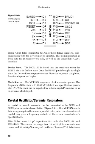
Figure 5.20b
MCP2150 pin’s PDA Robotics
pyhsical layout.
Timer (OST) delay (parameter 32). Once these delays complete, com-
munication with the device may be initiated. This communication is
from both the IR transceiver’s side, as well as the controller’s UART
interface.
Device Reset. The MCP2150 is forced into the reset state when the
RESET pin is in the low state. Once the RESET pin is brought to a high
state, the Device Reset sequence occurs. Once the sequence completes,
functional operation begins.
Clock Source. The MCP2150 requires a clock source to operate. The
frequency of this clock is 11.0592 MHz (electrical specification param-
eter 1A). This clock can be supplied by either a crystal/resonator or as
an external clock input.
Crystal Oscillator/Ceramic Resonators
A crystal or ceramic resonator can be connected to the OSC1 and
OSC2 pins to establish oscillation (Figure 5.21). The MCP2150 oscil-
lator design requires the use of a parallel cut crystal. Use of a series cut
crystal may give a frequency outside of the crystal manufacturer’s
specifications.
PDA Robot uses 22 pf capacitors for both the MCP2150 and
PIC16F876. The values can range from 10 to 22 pf for a ceramic res-
onator and 15 to 30 pf for a crystal oscillator. Because PDA Robot uses
62