
Page 88 - PDA Robotics Using Your Personal Digital Assistant to Control Your Robot
P. 88
PDA 05 5/30/03 11:35 AM Page 64
PDA Robotics
Transmitting
When the controller sends serial data to the MCP2150, the controller’s
baud rate is required to match the baud rate of the MCP2150’s serial port.
Receiving
When the controller receives serial data from the MCP2150, the con-
troller’s baud rate is required to match the baud rate of the MCP2150’s
serial port. Matching up the baud rate of the microcontroller to that set
by the DIP switches is done in the software that is loaded into PDA
Robot’s microcontroller. Chapter 7: Programming the PIC16F876
Microcontroller explains this in detail.
Modulation
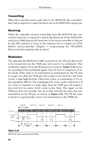
The data that the MCP2150 UART received (on the TX pin) that needs
to be transmitted (on the TXIR pin) will need to be modulated. This
modulated signal drives the IR transceiver module. Figure 5.22 shows
the encoding of the modulated signal. Each bit time is comprised of 16-
bit clocks. If the value to be transmitted (as determined by the TX pin)
is a logic low, then the TXIR pin will output a low level for 7-bit clock
cycles, a logic high level for 3-bit clock cycles, or a minimum of 1.6 µs.
(see parameter IR121). The remaining 6-bit clock cycles will be low. If
the value to transmit is a logic high, then the TXIR pin will output a
low level for the entire 16-bit clock cycles. Note: The signal on the
TXIR pin does not actually line up in time with the bit value that was
transmitted on the TX pin, as shown in Figure 5.22. The TX bit value
is shown to represent the value to be transmitted on the TXIR pin.
Figure 5.22
MCP2150 data encoding (modulated).
64