
Page 104 - Packed bed columns for absorption, desorption, rectification and direct heat transfer
P. 104
99
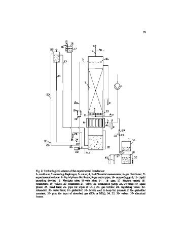
Fig. 2. Technological scheme of the experimental installation:
1- ventilator, 2-mesuring diaphragm; 3- valve; 4, S- differential manometers; 6- gas distributor; 7-
experimental column: 8- liquid phase distributor; 9-gas outlet pipe; 10- supporting grid; 11- liquid
sampling device; 12- Plexiglas tube; 13-weir pipe; 14 - 16- laps; 17- Mariott vessel; 18-
rotameters; 19- valves; 20- rotameter; 21- valve; 22- circulation pump; 23, 24 pipes for liquid
phase; 25- head tank; 26- pipe for input of CO2; 27- gas bottles; 28- regulating valve; 29-
rotameter; 30- water tank; 31- gasholder; 32- device used to keep the pressure in the gasholder
constant; 33- pipe for input of absorbed gas (SOa or NH3); 34, 35, 36- valves: 37- electrical
heater.