
Page 109 - Packed bed columns for absorption, desorption, rectification and direct heat transfer
P. 109
104
m . Because the corresponding orifices of every of the three distributors are on
one and the same vertical axis, the overall number of the orifices for the
2
distributor as a whole can be considered 923 orifices per m .
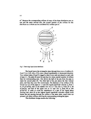
Fig. 5. Three-stage liquid phase distributor.
The liquid leaves the rectangular pipes through three rows of orifices (3,
4 and 5) on both sides of the pipes, placed equidistantly in horizontal direction.
Two vertical plates (8 and 9) cogged in their lower ends are placed on each side
of pipe (1). The plate (8) near the pipe has two times smaller number of orifices
than the corresponding pipe. This allows the half of the jets from the pipe to
reach the second plate (9). The other half of the jets meets the first vertical
plate, and then they also flow downwards. The diameter of the orifices of the
lowest row (5) of the pipes is 1.5 mm (for liquid superficial velocity Lh from 5
3
2
to 10 m /(m h)), that of the middle row (4) is 3 mm (for L h from 20 to 40
3 2
m /(m h)), and that of the upper row is 5.5 mm (for Lh from 80 to 200
2
3
m /(m h)). In order to avoid the interference of a part of the liquid phase
flowing onto plate (8) at the highest liquid superficial velocities which could
hinder the jets passing through the orifices of the same plate, small tubes are
pressed onto these orifices, reaching the corresponding rectangular pipes.
The distributor design ensures the following: