
Page 156 - Phase Space Optics Fundamentals and Applications
P. 156
The Radon-Wigner Transform 137
4 2 4 2
Spatial frequency (a.u.) –2 0 Spatial frequency (a.u.) –2 0
–4 –4
–2 –1 0 1 2 –2 –1 0 1 2
Spatial coordinate (mm) Spatial coordinate (mm)
(a) (b)
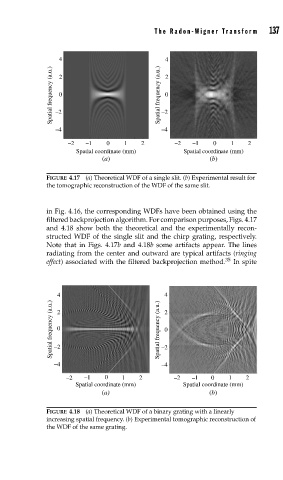
FIGURE 4.17 (a) Theoretical WDF of a single slit. (b) Experimental result for
the tomographic reconstruction of the WDF of the same slit.
in Fig. 4.16, the corresponding WDFs have been obtained using the
filtered backprojection algorithm. For comparison purposes, Figs. 4.17
and 4.18 show both the theoretical and the experimentally recon-
structed WDF of the single slit and the chirp grating, respectively.
Note that in Figs. 4.17b and 4.18b some artifacts appear. The lines
radiating from the center and outward are typical artifacts (ringing
effect) associated with the filtered backprojection method. 35 In spite
4 2 4
Spatial frequency (a.u.) 0 Spatial frequency (a.u.) 2 0
–2
–4 –2
–4
–2 –1 0 1 2 –2 –1 0 1 2
Spatial coordinate (mm) Spatial coordinate (mm)
(a) (b)
FIGURE 4.18 (a) Theoretical WDF of a binary grating with a linearly
increasing spatial frequency. (b) Experimental tomographic reconstruction of
the WDF of the same grating.