
Page 154 - Phase Space Optics Fundamentals and Applications
P. 154
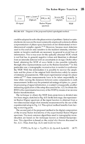
The Radon-Wigner Transform     135


                          RWT =⎜FrFT ⎜ 2            Inverse RT
                   f (x)                RW (x, θ)               W (x, ξ)
                                                                  f
                                           f
                             (Optical)                (digital)
                 1D signal             Radon Wigner              WDF
                                         spectrum
               FIGURE 4.15 Diagram of the proposed hybrid optodigital method.


               could be adapted to solve the phase retrieval problem. Optical or opto-
               electronic devices are the most commonly employed systems to obtain
               a representation of phase-space functions of one-dimensional or two-
               dimensional complex signals. 31,32  However, because most detectors
               used to this end are only sensitive to the incident intensity, interfero-
               metric or iterative methods are necessary in general to avoid loss of
               information. This is true even for the optically obtained WDF, which
               is real but has, in general, negative values and therefore is obtained
               from an intensity detector with an uncertainty in its sign. On the other
               hand, obtaining the WDF of wave fields is also possible indirectly
               through other representations such as the Radon transform. 33  In this
               particular case, a tomographic reconstruction is needed to synthesize
               the WDF. With this information it is possible to recover the ampli-
               tude and the phase of the original field distribution solely by means
               of intensity measurements. With most experimental setups for phase
               retrieval, 29,30  these measurements have to be taken sequentially in
               time while varying the distances between some components in each
               measurement. In this way the potential advantage of optics, i.e., paral-
               lel processing of signal information, is wasted. Consequently, another
               interesting application of the setup discussed in Sec. 4.2.2 to obtain the
               RWD is the experimental recovery of the WDF by means of an inverse
               Radon transformation.
                 The technique to obtain the WDF from projections is divided into
               two basic stages, sketched in Fig. 4.15. In the first stage, the experimen-
               tal Radon-Wigner spectrum of the input function is obtained from a
               two-dimensional single-shot intensity measurement by the use of the
               experimental setup in Fig. 4.4. This optical method benefits from hav-
               ing no moving parts.
                 The second part of the proposed method is the digital computation
               of the inverse Radon transforms of the experimental Radon-Wigner
               spectrum. The most common algorithms used in tomographic recon-
               struction are based on the technique known as filtered backprojec-
               tion. This algorithm is based on the central slice theorem discussed in
               Sec. 4.2.1. Thus, from Eqs. (4.21) and (4.22) we have


                      F{RW f (x   ,  ),     }= F 2D {W f (x,  ), (    cos  ,     sin  )}  (4.77)