Page 149 - Phase Space Optics Fundamentals and Applications
P. 149

130   Chapter Four


                  1000                        1000
                        W = 0                  750   W = λ/2
                                                      40
                          40
                          α = 0°
                 Irradiance (a.u.)  500        500
                                                      α = 0°
                   750
                   250

                                                0
                    0                          250
                   15                          15
                        W = 0                        W = λ/2
                                                      40
                          40
                          α = 0.012°
                                                      α = 0.012°
                 Irradiance (a.u.)  10 5       10
                                                5


                    0                           0
                    8                           8
                        W = 0                        W = λ/2
                          40                    6     40
                          α = 0.024°
                                                      α = 0.024°
                 Irradiance (a.u.)  4           4
                    6

                    2

                    0                           2 0
                    –4.0  –2.0  0.0  2.0   4.0   –4.0  –2.0  0.0  2.0  4.0
                                    Defocus coefficient: W  (μm)
                                                     20
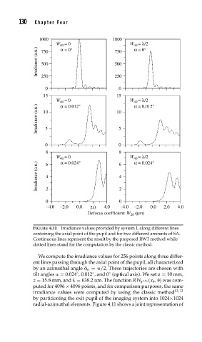
               FIGURE 4.11 Irradiance values provided by system I, along different lines
               containing the axial point of the pupil and for two different amounts of SA.
               Continuous lines represent the result by the proposed RWT method while
               dotted lines stand for the computation by the classic method.

                 We compute the irradiance values for 256 points along three differ-
               ent lines passing through the axial point of the pupil, all characterized
               by an azimuthal angle 	 o =  /2. These trajectories are chosen with
               tilt angles   = 0.024 ,0.012 , and 0 (optical axis). We set a = 10 mm,
                                ◦
                                      ◦
                                            ◦
                                                          ,  o (x   ,  ) was com-
                z = 15.8 mm, and   = 638.2 nm. The function RW q
               puted for 4096 × 4096 points, and for comparison purposes, the same
               irradiance values were computed by using the classic method 12,13
               by partitioning the exit pupil of the imaging system into 1024×1024
               radial-azimuthal elements. Figure 4.11 shows a joint representation of
   144   145   146   147   148   149   150   151   152   153   154