
Page 223 - Phase Space Optics Fundamentals and Applications
P. 223
204 Chapter Six
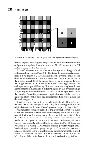
8 4
2 1
FIGURE 6.5 Schematic sketch of gray-level coding mask for binary objects.
imaged object. Obviously, the imager should have a sufficient number
2
of dynamic range bits. It should be at least M× K , where K is the SR
factor in every spatial dimension.
To clarify this concept, the schematic description of the gray level
coding mask appears in Fig. 6.5. In this figure the resolution improve-
ment is by a factor of 2 in each axis; thus the dynamic range of the
detector should have 4 times more bits than the number of bits in
the original object. So if the sensor has a dynamic range of 12 bits,
the imaged object should not have more than 3 bits of gray level. This
coding causes a spatial blurring. However, since every high resolution
lateral feature is mapped to a different region in the dynamic range
axis, it may be recovered later on. This is so because a priori we know
the encoding/decoding conversion map that converts between every
high-resolution spatial pixel and its corresponding bits region in the
dynamic range axis.
Specifically referring again to the schematic sketch of Fig. 6.5, since
the ratio of two adjacent pixels of the gray-level coding mask is 2, the
original object should have 1 bit of dynamic range (a binary object).
An important comment related to this approach is that it is more
suitable to deal with the reduction of the imaging resolution due to ge-
ometric limitation (the number and the size of detector’s pixels) than
the diffraction limitation since the proper conversion between space
resolution and dynamic range bits is done not continuously in space
but only for spatially adjacent blocks of pixels (in Fig. 6.5 those are
blocks of 2 × 2 pixels). The approach will not perform proper gray-
level coding for spatial sampling in regions of transition between two
adjacent blocks (e.g., the spatial transition sample which is the blurred
value that averages the right column of pixels of one block with the
left column of the next adjacent block positioned on its right side).