
Page 228 - Phase Space Optics Fundamentals and Applications
P. 228
Super Resolved Imaging in Wigner-Based Phase Space 209
distribution used to encode the information as in Fig. 6.8a. The decod-
ing is designated by thin, long rectangles having spectral dimensions
of 3 , which correspond to the highest spatial resolution that we
aim to image. Those rectangles select out or filter out of the spatially
blurred information (that is designated with short, wide rectangles
having spectral width of ) the relevant gray-level information of
each high-resolution pixel (having dimension of x/3). Obviously the
decoding that is presented in Fig. 6.8c is relevant only to the wave-
length multiplexing case since in the dynamic range case the decod-
ing is trivial: one only needs to pick up the relevant bits, knowing
that every group of bits is related to a different high-resolution spatial
allocation.
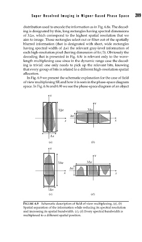
In Fig. 6.9 we present the schematic explanation for the case of field
of view multiplexing SR and how it is seen in the phase-space diagram
space. In Fig. 6.9a and 6.9b we see the phase-space diagram of an object
ν
ν
3Δν 3Δx
Δν
x x
Δx
(a) (b)
ν
ν
3Δν 3Δx
Δν
x x
Δx
(c) (d)
FIGURE 6.9 Schematic description of field of view multiplexing. (a), (b)
Spatial separation of the information while reducing its spectral resolution
and increasing its spatial bandwidth. (c), (d) Every spectral bandwidth is
multiplexed to a different spatial position.