
Page 322 - Phase Space Optics Fundamentals and Applications
P. 322
Self-Imaging in Phase Space 303
G
G 1 2 L O
Incoherent
illumination
z
d
z L f f
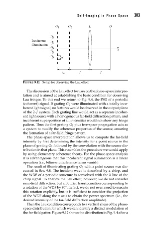
FIGURE 9.11 Setup for observing the Lau effect.
The discussion of the Lau effect focuses on the phase-space interpre-
tation and is aimed at establishing the basic condition for observing
Lau fringes. To this end we return to Fig. 9.4, the PSD of a periodic
(coherent) signal. If grating G 2 were illuminated with a totally inco-
herent light signal, no features would be observed in the output plane
of the 2- f system. Each grating line would act as a separate incoher-
ent light source with a homogeneous far-field diffraction pattern, and
incoherent superposition of all intensities would not show any fringe
pattern. Thus the first grating G 1 plus free-space propagation acts as
a system to modify the coherence properties of the source, ensuring
the formation of a far-field fringe pattern.
The phase-space interpretation allows us to compute the far-field
intensity by first determining the intensity for a point source in the
plane of grating G 1 followed by the convolution with the source dis-
tribution in that plane. This resembles the procedure we would apply
by using elementary coherence theory. For the phase-space analysis
it is advantageous that this incoherent signal summation is a linear
operation (i.e., bilinear interference terms vanish).
The result of illuminating grating G 2 with a point source was dis-
cussed in Sec. 9.8. The incident wave is described by a chirp, and
the WDF of a periodic structure is convolved with the line of the
chirp signal. To analyze the Lau effect, however, we do not consider
near-field diffraction, but a Fourier transformation corresponding to
a rotation of the WDF by 90 . In fact, we do not even need to execute
◦
this rotation explicitly, but it is sufficient to consider the projection
of the WDF along the x axis to obtain the power spectrum (i.e., the
desired intensity of the far-field diffraction amplitude).
Then the Lau condition corresponds to a vertical shear of the phase-
space distribution for which we can identify a distinct modulation of
the far-field patter. Figure 9.12 shows the distribution in Fig. 9.4 after a