
Page 91 - Phase Space Optics Fundamentals and Applications
P. 91
72 Chapter Three
(a) (b)
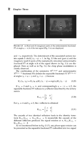
FIGURE 3.3 (a) Real and (b) imaginary parts of the antisymmetric fractional
FT at angle
= /4 of the test signal (Fig. 3.1a) are displayed.
and − , respectively. The determinant of the associated unitary ma-
trix equals 1: det U f ( , − ) = 1. In Fig. 3.3 the real (part a) and the
imaginary (part b) parts of the numerically simulated antisymmetric
fractional FT at angle /4 of the signal shown in Fig. 3.1a are dis-
played. Here as well as in Fig. 3.2, the chirp phase modulation is
clearly observed.
U f (
,
)
The combination of the symmetric R and antisymmetric
U f ( ,− ) U f ( x , y )
R fractional FTs defines the separable fractional FT R
at angles x =
+ and y =
− because
U f ( x , y ) = U f (
,
)U f ( , − ) = exp(i
)U f ( , − ) (3.29)
If x = 0 and y = , and correspondingly
=− = /2, the
separable fractional FT reduces to y reflector described by the unitary
matrix
1 0
= (3.30)
0 −1
U re f y
For x = and y = 0, the x reflector is obtained
−10
= (3.31)
0 1
U re f x
The cascade of two identical reflectors leads to the identity trans-
= I; meanwhile the cascade of the
form U re f y U re f y = U re f x U re f x
=
different reflectors produces the signal rotation at , U re f x U re f y
=−I.
U re f y U re f x
As we mentioned before in Eq. (3.17), any phase-space rotator can
be presented as the separable fractional FT embedded into two signal