
Page 134 - Phase-Locked Loops Design, Simulation, and Applications
P. 134
MIXED-SIGNAL PLL ANALYSIS Ronald E. Best 85
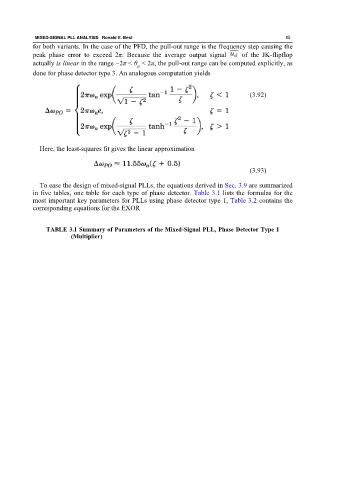
for both variants. In the case of the PFD, the pull-out range is the frequency step causing the
peak phase error to exceed 2π. Because the average output signal of the JK-flipflop
actually is linear in the range −2π < θ < 2π, the pull-out range can be computed explicitly, as
e
done for phase detector type 3. An analogous computation yields
(3.92)
Here, the least-squares fit gives the linear approximation
(3.93)
To ease the design of mixed-signal PLLs, the equations derived in Sec. 3.9 are summarized
in five tables, one table for each type of phase detector. Table 3.1 lists the formulas for the
most important key parameters for PLLs using phase detector type 1, Table 3.2 contains the
corresponding equations for the EXOR
TABLE 3.1 Summary of Parameters of the Mixed-Signal PLL, Phase Detector Type 1
(Multiplier)