
Page 140 - Phase-Locked Loops Design, Simulation, and Applications
P. 140
MIXED-SIGNAL PLL ANALYSIS Ronald E. Best 88
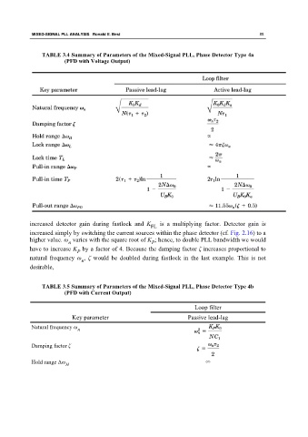
TABLE 3.4 Summary of Parameters of the Mixed-Signal PLL, Phase Detector Type 4a
(PFD with Voltage Output)
increased detector gain during fastlock and K is a multiplying factor. Detector gain is
FL
increased simply by switching the current sources within the phase detector (cf. Fig. 2.16) to a
higher value. ω varies with the square root of K ; hence, to double PLL bandwidth we would
n
P
have to increase K by a factor of 4. Because the damping factor ζ increases proportional to
P
natural frequency ω , ζ would be doubled during fastlock in the last example. This is not
n
desirable,
TABLE 3.5 Summary of Parameters of the Mixed-Signal PLL, Phase Detector Type 4b
(PFD with Current Output)
Loop filter
Key parameter Passive lead-lag
Natural frequency ω
n
Damping factor ζ
Hold range Δω ∞
H