
Page 142 - Phase-Locked Loops Design, Simulation, and Applications
P. 142
MIXED-SIGNAL PLL ANALYSIS Ronald E. Best 89
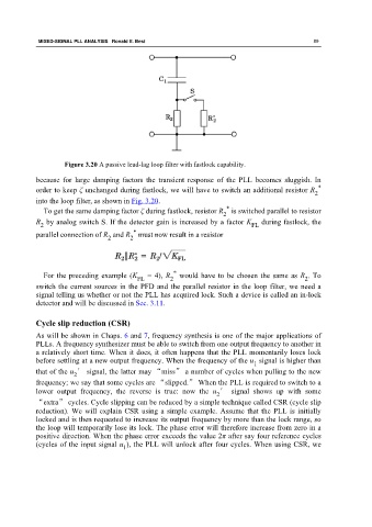
Figure 3.20 A passive lead-lag loop filter with fastlock capability.
because for large damping factors the transient response of the PLL becomes sluggish. In
*
order to keep ζ unchanged during fastlock, we will have to switch an additional resistor R
2
into the loop filter, as shown in Fig. 3.20.
*
To get the same damping factor ζ during fastlock, resistor R is switched parallel to resistor
2
R by analog switch S. If the detector gain is increased by a factor K during fastlock, the
2 FL
*
parallel connection of R and R must now result in a resistor
2
2
*
For the preceding example (K = 4), R would have to be chosen the same as R . To
2
2
FL
switch the current sources in the PFD and the parallel resistor in the loop filter, we need a
signal telling us whether or not the PLL has acquired lock. Such a device is called an in-lock
detector and will be discussed in Sec. 3.11.
Cycle slip reduction (CSR)
As will be shown in Chaps. 6 and 7, frequency synthesis is one of the major applications of
PLLs. A frequency synthesizer must be able to switch from one output frequency to another in
a relatively short time. When it does, it often happens that the PLL momentarily loses lock
before settling at a new output frequency. When the frequency of the u signal is higher than
1
that of the u ′ signal, the latter may “miss” a number of cycles when pulling to the new
2
frequency; we say that some cycles are “slipped.” When the PLL is required to switch to a
lower output frequency, the reverse is true: now the u ′ signal shows up with some
2
“extra” cycles. Cycle slipping can be reduced by a simple technique called CSR (cycle slip
reduction). We will explain CSR using a simple example. Assume that the PLL is initially
locked and is then requested to increase its output frequency by more than the lock range, so
the loop will temporarily lose its lock. The phase error will therefore increase from zero in a
positive direction. When the phase error exceeds the value 2π after say four reference cycles
(cycles of the input signal u ), the PLL will unlock after four cycles. When using CSR, we
1