
Page 172 - Phase-Locked Loops Design, Simulation, and Applications
P. 172
PLL PERFORMANCE IN THE PRESENCE OF NOISE Ronald E. Best 106
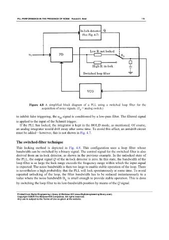
Figure 4.8 A simplified block diagram of a PLL using a switched loop filter for the
acquisition of noisy signals. (S = analog switch.)
A
to inhibit false triggering, the u signal is conditioned by a low-pass filter. The filtered signal
M
is applied to the input of the Schmitt trigger.
If the PLL has locked, the integrator is kept in the HOLD mode, as mentioned. Of course,
an analog integrator would drift away after some time. To avoid this effect, an antidrift circuit
must be added—however, this is not shown in Fig. 4.7.
The switched-filter technique
This locking method is depicted in Fig. 4.8. This configuration uses a loop filter whose
bandwidth can be switched by a binary signal. The control signal for the switched filter is also
derived from an in-lock detector, as shown in the previous example. In the unlocked state of
the PLL, the output signal Q of the in-lock detector is zero. In this state, the bandwidth of the
loop filter is so large the lock range exceeds the frequency range within which the input signal
is expected. The noise bandwidth is then too large to enable stable operation of the loop. There
is nevertheless a high probability that the PLL will lock spontaneously at some time. To avoid
repeated unlocking of the loop, the filter bandwidth has to be reduced instantaneously to a
value where the noise bandwidth B is small enough to provide stable operation. This is done
L
by switching the loop filter to its low-bandwidth position by means of the Q signal.
Printed from Digital Engineering Library @ McGraw-Hill (www.Digitalengineeringlibrary.com).
Copyright ©2004 The McGraw-Hill Companies. All rights reserved.
Any use is subject to the Terms of Use as given at the website.