
Page 204 - Phase-Locked Loops Design, Simulation, and Applications
P. 204
MIXED-SIGNAL PLL APPLICATIONS PART 1: INTEGER-N FREQUENCY
SYNTHESIZERS Ronald E. Best 125
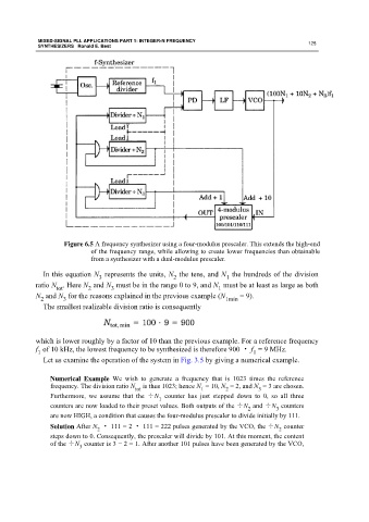
Figure 6.5 A frequency synthesizer using a four-modulus prescaler. This extends the high-end
of the frequency range, while allowing to create lower frequencies than obtainable
from a synthesizer with a dual-modulus prescaler.
In this equation N represents the units, N the tens, and N the hundreds of the division
1
3
2
ratio N . Here N and N must be in the range 0 to 9, and N must be at least as large as both
tot 2 3 1
N and N for the reasons explained in the previous example (N 1min = 9).
2
3
The smallest realizable division ratio is consequently
which is lower roughly by a factor of 10 than the previous example. For a reference frequency
f of 10 kHz, the lowest frequency to be synthesized is therefore 900 · f = 9 MHz.
1
1
Let us examine the operation of the system in Fig. 3.5 by giving a numerical example.
Numerical Example We wish to generate a frequency that is 1023 times the reference
frequency. The division ratio N is thus 1023; hence N = 10, N = 2, and N = 3 are chosen.
2
tot
1
3
Furthermore, we assume that the ÷N counter has just stepped down to 0, so all three
1
counters are now loaded to their preset values. Both outputs of the ÷N and ÷N counters
2
3
are now HIGH, a condition that causes the four-modulus prescaler to divide initially by 111.
Solution After N · 111 = 2 · 111 = 222 pulses generated by the VCO, the ÷N counter
2
2
steps down to 0. Consequently, the prescaler will divide by 101. At this moment, the content
of the ÷N counter is 3 − 2 = 1. After another 101 pulses have been generated by the VCO,
3