
Page 208 - Phase-Locked Loops Design, Simulation, and Applications
P. 208
MIXED-SIGNAL PLL APPLICATIONS PART 1: INTEGER-N FREQUENCY
SYNTHESIZERS Ronald E. Best 127
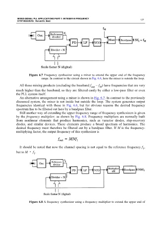
Figure 6.7 Frequency synthesizer using a mixer to extend the upper end of the frequency
range. In contrast to the circuit shown in Fig. 6.6, here the mixer is outside the loop.
All these mixing products (excluding the baseband f out − f ) have frequencies that are very
M
much higher than the baseband, so they are filtered easily by either a low-pass filter or even
the PLL system itself.
An alternative arrangement using a mixer is shown in Fig. 6.7. In contrast to the previously
discussed system, the mixer is not inside but outside the loop. The system generates output
frequencies identical with those in Fig. 6.6, but for obvious reasons the desired frequency
spectrum has to be filtered out here by a bandpass filter.
Still another way of extending the upper frequency range of frequency synthesizers is given
by the frequency multiplier, as shown by Fig. 6.8. Frequency multipliers are normally built
from nonlinear elements that produce harmonics, such as varactor diodes, step-recovery
diodes, and similar devices. These elements produce a broad spectrum of harmonics. The
desired frequency must therefore be filtered out by a bandpass filter. If M is the frequency-
multiplying factor, the output frequency of this synthesizer is
It should be noted that now the channel spacing is not equal to the reference frequency f ,
1
but to M · f .
1
Figure 6.8 A frequency synthesizer using a frequency multiplier to extend the upper end of