
Page 206 - Phase-Locked Loops Design, Simulation, and Applications
P. 206
MIXED-SIGNAL PLL APPLICATIONS PART 1: INTEGER-N FREQUENCY
SYNTHESIZERS Ronald E. Best 126
The content of the ÷N counter is now 7. After another 700 pulses have been generated
1
by the VCO, the ÷N counter also steps down to 0, and the cycle is repeated. To step
1
through an entire cycle, the VCO had to produce a total of
pulses, which is exactly the number desired.
Extending the Frequency Range with Mixers and Frequency Multipliers
In all frequency synthesizer systems previously considered, multiples of a reference frequency
have been generated exclusively by scaling down the VCO output signal by various counter
configurations. To produce frequencies in the range of 98.7 to 118.7 MHz with a spacing of
100 kHz, a synthesizer circuit would have had to be designed to offer an overall division ratio
of 987 to 1187. As an alternative, one could first generate output frequencies in the range of
8.7 to 18.7 MHz, using a division ratio of 87 to 187, and then mix up the obtained frequency
band to the desired band. An additional local oscillator operating at a frequency of 90 MHz
would be required in this case.
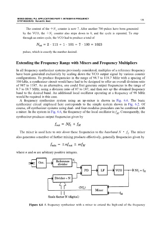
A frequency synthesizer system using an up-mixer is shown in Fig. 6.6. The basic
synthesizer circuit employed here corresponds to the simple system shown in Fig. 6.2. Of
course, all synthesizer systems using dual- and four-modulus prescalers can be combined with
a mixer. In the system in Fig. 6.6, the frequency of the local oscillator is f . Consequently, the
M
synthesizer produces output frequencies given by
The mixer is used here to mix down these frequencies to the baseband N · f . The mixer
1
also generates a number of further mixing products effectively, generally frequencies given by
where n and m are arbitrary positive integers.
Figure 6.6 A frequency synthesizer with a mixer to extend the high-end of the frequency