
Page 212 - Phase-Locked Loops Design, Simulation, and Applications
P. 212
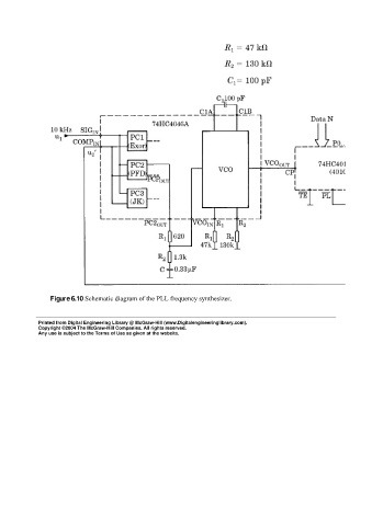
Figure 6.10 Schematic diagram of the PLL frequency synthesizer.


             Printed from Digital Engineering Library @ McGraw-Hill (www.Digitalengineeringlibrary.com).
             Copyright ©2004 The McGraw-Hill Companies. All rights reserved.
             Any use is subject to the Terms of Use as given at the website.