
Page 216 - Phase-Locked Loops Design, Simulation, and Applications
P. 216
MIXED-SIGNAL PLL APPLICATIONS PART 1: INTEGER-N FREQUENCY
SYNTHESIZERS Ronald E. Best 132
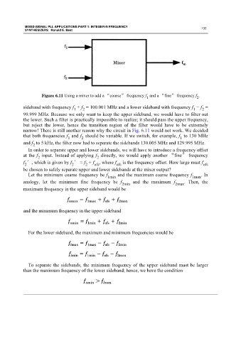
Figure 6.11 Using a mixer to add a “coarse” frequency f and a “fine” frequency f .
1
2
sideband with frequency f + f = 100.001 MHz and a lower sideband with frequency f − f =
1 2 1 2
99.999 MHz. Because we only want to keep the upper sideband, we would have to filter out
the lower. Such a filter is practically impossible to realize; it should pass the upper frequency,
but reject the lower, hence the transition region of the filter would have to be extremely
narrow! There is still another reason why the circuit in Fig. 6.11 would not work. We decided
that both frequencies f and f should be variable. If we switch, for example, f to 130 MHz
1
1
2
and f to 5 kHz, the filter now had to separate the sidebands 130.005 MHz and 129.995 MHz.
2
In order to separate upper and lower sidebands, we will have to introduce a frequency offset
at the f input. Instead of applying f directly, we would apply another “fine” frequency
2 2
f ′, which is given by f ′ = f + f ofs , where f ofs is the frequency offset. How large must f ofs
2
2
2
be chosen to safely separate upper and lower sidebands at the mixer output?
Let the minimum coarse frequency be f and the maximum coarse frequency f . In
1min 1max
analogy, let the minimum fine frequency be f 2min and the maximum f 2max . Then, the
maximum frequency in the upper sideband would be
and the minimum frequency in the upper sideband
For the lower sideband, the maximum and minimum frequencies would be
To separate the sidebands, the minimum frequency of the upper sideband must be larger
than the maximum frequency of the lower sideband; hence, we have the condition