
Page 220 - Phase-Locked Loops Design, Simulation, and Applications
P. 220
MIXED-SIGNAL PLL APPLICATIONS PART 1: INTEGER-N FREQUENCY
SYNTHESIZERS Ronald E. Best 134
spacing 1 kHz. A second mixer Mix2 is used now to add a frequency offset of 70 MHz. Again
Mix2 generates an upper and a lower sideband. The upper ranges from 75 to 75.999 MHz, the
lower from 64.001 to 65 MHz. Because we use only the upper sideband, it is filtered out by a
bandpass filter with center frequency of about 75.5 MHz. The one-sided bandwidth must be
somewhat larger than about 0.5 MHz.
Multi-loop synthesizers are frequently found in signal generators, receivers, transmitters
(for instance, short wave), and the like. Very sophisticated multi-loop designs have been
described by Rohde. 48, 49
Phase Noise and Spurs in Integer Frequency Synthesizers
Having designed a PLL frequency synthesizer that uses a highly stable quartz-crystal reference
oscillator, we may hope to get a nicely clean output signal with high frequency stability and no
phase jitter. Mathematically, the spectrum of the synthesizer’s output signal should consist of
just one single line at the desired frequency. Unfortunately, reality shows another picture:
when measuring the signal spectrum, we may observe quite a bit of phase jitter; moreover, we
can detect a couple of sidebands (so called “spurs”) around the desired center frequency.
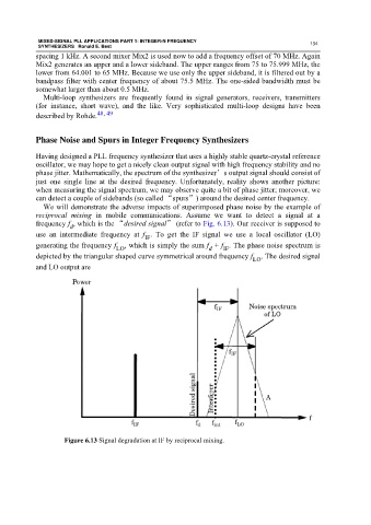
We will demonstrate the adverse impacts of superimposed phase noise by the example of
reciprocal mixing in mobile communications. Assume we want to detect a signal at a
frequency f , which is the “desired signal” (refer to Fig. 6.13). Our receiver is supposed to
d
use an intermediate frequency at f . To get the IF signal we use a local oscillator (LO)
IF
generating the frequency f , which is simply the sum f + f . The phase noise spectrum is
LO d IF
depicted by the triangular shaped curve symmetrical around frequency f . The desired signal
LO
and LO output are
Figure 6.13 Signal degradation at IF by reciprocal mixing.