
Page 218 - Phase-Locked Loops Design, Simulation, and Applications
P. 218
MIXED-SIGNAL PLL APPLICATIONS PART 1: INTEGER-N FREQUENCY
SYNTHESIZERS Ronald E. Best 133
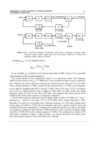
Figure 6.12 A dual-loop frequency synthesizer built from a synthesizer creating coarse
frequency steps (1 MHz, upper part) and from another synthesizer creating fine
frequency steps (1 kHz, lower part).
Assuming f 2min = 0, this inegality leads to
In our example, f ofs would have to be chosen larger than 50 MHz. Figure 6.12 is a possible
implementation of the intended synthesizer.
The circuit consists of two synthesizers; hence, it is a dual-loop system. The frequency
offset has been chosen to be f ofs = 75 MHz here. Let us consider the upper (coarse) synthesizer
first. Without mixer Mix1, this loop would create frequencies in the range of 25 to 125 MHz,
with a channel spacing of 1 MHz. Assume for the moment that f = 0—that is, the frequency
2
at the output of bandpass filter BP2 is exactly 75 MHz. Due to the mixer, VCO1 is forced to
now create an output frequency that is higher by that offset—in other words, the output
frequency range of VCO1 is now 100 to 200 MHz. The bandpass filter filters out the lower
sideband only; hence, Mix1 operates as a frequency subtractor.
Now the fine frequency component must be added. With an offset of 75 MHz, the “fine”
frequency f ′ must be in the range of 75 to 75.999 MHz with a channel spacing of 1 kHz.
2
Basically, we could use a synthesizer with a reference frequency of 1 kHz and a scaling factor
in the range of 75,000 to 75,999, but we remember that such a circuit would be slow and
would have bad noise performance. Looking at the synthesizer in the lower part of the figure
we recognize a synthesizer with reference 10 kHz instead of 1 kHz, creating a frequency range
from 50 to 59.990 MHz with a channel spacing of 10 kHz. This synthesizer is a factor of 10
faster than a synthesizer using a 1 kHz reference. An external divide-by-10 counter scales
down that range to between 5 and 5.999 MHz with a channel