
Page 222 - Phase-Locked Loops Design, Simulation, and Applications
P. 222
MIXED-SIGNAL PLL APPLICATIONS PART 1: INTEGER-N FREQUENCY
SYNTHESIZERS Ronald E. Best 135
fed to a mixer that creates the IF signal. Now assume that an interfering signal is present at
frequency f , which is not far away from f , may be at a distance of only 200 kHz from f .
d,
d
int
This could be another communication signal that has perhaps a much greater amplitude than
the desired signal. If the spectrum of the LO at frequency f + f shows appreciable
int
IF
amplitude (as shown by line A in the figure), the interferer is also mixed down to the
intermediate frequency. This phenomenon is called reciprocal mixing. When the interfering
signal is 100 dB greater than that desired and the noise spectrum of the LO is “only” 100
dB below its carrier amplitude, these two signals produce the same mixer output power. In
many mobile communications, the individual channels are spaced by 200 kHz. To avoid
reciprocal mixing by an interferer whose frequency is immediately adjacent to the desired
channel frequency, the noise spectrum of the LO must be markedly more than 100 dB below
the carrier amplitude at a distance of 200 kHz from that carrier. Frequency synthesizers
intended for such applications impose, therefore, very tight requirements on phase noise and
spurs. It should be noted that in many applications the IF frequency f is chosen 0 (zero IF
IF
systems).
In the following, we will investigate the sources of those undesired noise components. The
mathematical analysis is quite cumbersome, but fortunately there are a number of models
available that greatly simplify the analysis. Basically, each part of the synthesizer circuit can
48
contribute to output phase jitter. In the following, we will concentrate on the dominant ones.
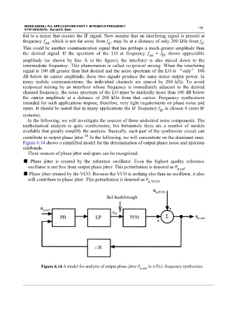
Figure 6.14 shows a simplified model for the determination of output phase noise and spurious
sidebands.
Three sources of phase jitter and spurs can be recognized:
■ Phase jitter is created by the reference oscillator. Even the highest quality reference
oscillator is not free from output phase jitter. This perturbation is denoted as θ n,ref .
■ Phase jitter created by the VCO. Because the VCO is nothing else than an oscillator, it also
will contribute to phase jitter. This perturbation is denoted as θ n,VCO .
Figure 6.14 A model for analysis of output phase jitter θ n,out in a PLL frequency synthesizer.